HTF HF-2 Series
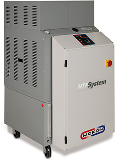
Mokon's HTF HF-2 Series heat transfer oil system provides accurate temperature control up to 600°F (315°C) with an option to go to 650°F (343°C) with improved performance, energy efficiency and reduced space requirements for large flow and higher heating capacity applications.
Unique Heating Design Maximizes Energy Efficiency
- Smaller hold-up volume of fluid results in faster heat up and cool down
- Longer heater and fluid life - unique flow pattern design and low watt density elements
Cool Oil Reservoir Design
- Separate cool oil reservoir isolates heating loop from cooling loop
- Continuous flow direct immersion heat exchanger eliminates thermal shock
- Reduces oxidation rate or breakdown of fluid in cool oil reservoir
- Only system designed to hold fluid in lower reservoir so fluid does not spill onto floor in event of a leak
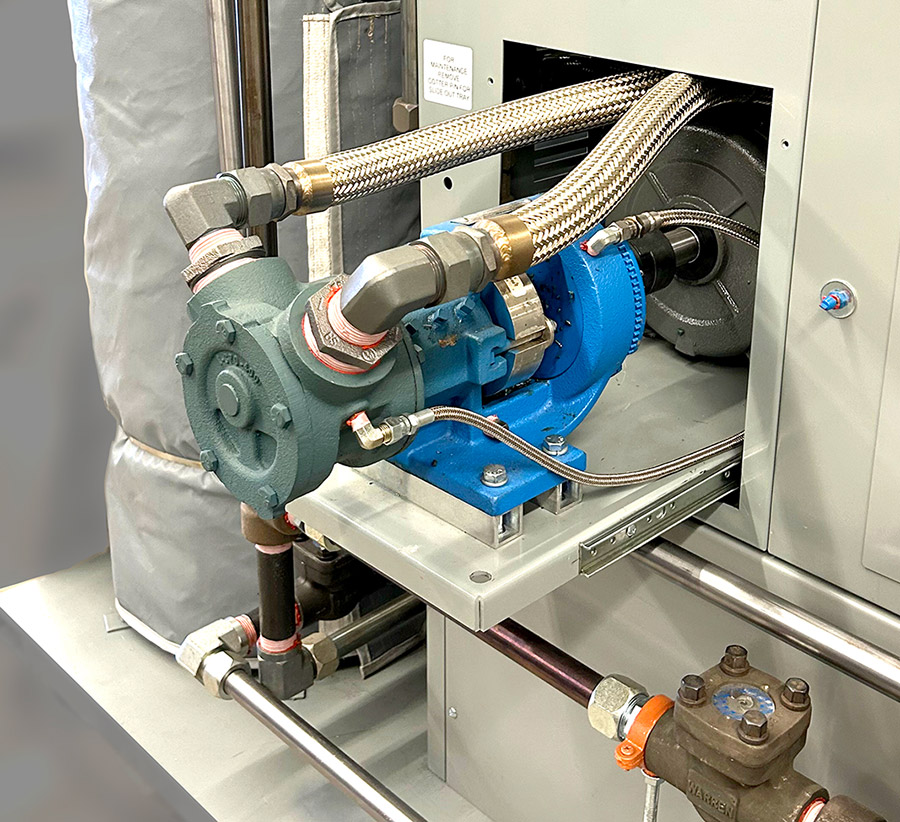
- Single or dual zone configurations
- Centrifugal pump
- TEFC (IP54 Rating) motor that meets/exceeds NEMA Premium Efficiency levels
- Energy efficient insulated heater manifold with stainless steel heating elements
- Cool oil reservoir design, utilizing a continuous flow heat exchanger for increased cooling efficiency which eliminates thermal shock and provides trim cooling
- Welded construction to minimize threaded connections
- 1/16 DIN non-proprietary microprocessor-based controller in easily accessible panel
- Low pressure shut-off switch
- Fluid high temperature shut-off switch
- Automatic air purge
- NEMA/Type 1 electrical enclosure
- Discharge pressure gauge
- Process and cooling water connections
- Low fluid level shut off
- Main power safety door disconnect switch
- Redundant heater contactor
- Y type strainer (shipped loose)
- Heavy-duty ball bearing casters for portability
- Powder-coated carbon steel cabinet
- cULus 508A labeled electrical subpanel
Additional Features:
- Warranty
- 1 year on system
- 5 years on standard microprocessor controller
Typical Flow Schematic

- Alarms – audible and visual
- Control options – remote setpoint and re-transmission, communication ports
- Cool down/automatic shut off via time delay relay
- Cooling only designs
- Emergency "crash" cooling control
- Emergency stop
- Fluid temperature ranges up to 650°F
- Heat exchanger flow control
- High/low heat switch for 12 kW units and higher
- High temperature rated hoses
- Increased cooling and heating capacities
- Inline heat exchangers
- Magnetic drive pumps
- Multi-zone sliding service tray for easy access and maintenance of pump/motor
- NEMA/Type 4, 4X, 7, and 12
- Nitrogen purge
- Other voltages, phases, frequencies
- Overhead piping kit
- Phase monitor
- Process fluid purge via air connection or switch
- Remote start/stop and control panels
- Solid state contactors/relays and SCR
- Stainless steel cabinets, fluid circuits and components
- Strainers (additional)
- Tank low level indication and system shutdown
- Thermocouple with selector switch
- Thermometers
- Timers
- UL, CSA, CE and EAC certifications
- Valved process bypass via metering globe
Please consult factory for more information.
Features of Standard and Optional Controls
A variety of controls are available from Mokon to enhance the high performance of our systems. From solid state to microprocessor based, with communication capabilities to PLC type controls, Mokon can provide the type of control package right for your process.
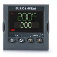
Eurotherm 3216 Series
The Eurotherm 1/16 DIN (3216) microprocessor controller is operator friendly and easy-to-use. Standard features include a microprocessor PID controller for the highest accuracy in temperature control, a dual LCD display that shows set point and actual fluid temperature, and scrolling text messages that deliver plain language messages to let users know exactly what is happening to the process. There are optional 1/8 or 1/4 DIN controllers available, with high/low deviation alarm, remote set point and retransmission and serial communication. A five-year warranty comes standard with the controller.
Eurotherm 3216 Spec Sheet
Eurotherm 3200 Series Manual
Custom Controls
Mokon's ability to meet customers' specific requirements is seen not only in custom system designs, but also in controls. Our engineers can custom design a control package that meets your specific processing needs, from brand name controls, to direct computer/host machine interfacing. All of which can be expected with the same quality and durability that our customers expect from our complete line of temperature control systems.
| Model |
|
# of Zones | Heating Capacity kW per Zone (total kW) | Cooling Heat Exchanger | Reservoir Volume (Gallons) | Approx. Dimensions (L x W x H) | Shipping Weight (Approx. lbs.) | |||||
|---|---|---|---|---|---|---|---|---|---|---|---|---|
| HF | 18.9 | 21.1 | 1 | 12 | 7.0 sq. ft. | 38 | 41″ x 30″ x 51″ | 620 | ||||
| HF | 33.9 | 36.1 | 1 | 24 | 7.0 sq. ft. | 38 | 41″ x 30″ x 51″ | 670 | ||||
| HF | 49 | 51.2 | 1 | 36 | 7.0 sq. ft. | 38 | 41″ x 30″ x 51″ | 730 | ||||
| HF | 64 | 66.2 | 1 | 48 | 7.0 sq. ft. | 38 | 41″ x 30″ x 62″ | 825 | ||||
| HF | 79.2 | 81.4 | 1 | 60 | 7.0 sq. ft. | 38 | 41″ x 30″ x 62″ | 950 | ||||
| HF | 94.2 | 96.4 | 1 | 72 | 7.0 sq. ft. | 38 | 41″ x 30″ x 74″ | 1,050 | ||||
| HF | 124.4 | 126.6 | 1 | 96 | 14.0 sq. ft. | 58 | 41″ x 45″ x 62″ | 1,300 | ||||
| HF | 37.7 | 42.1 | 2 | 12 (24) | 14.0 sq. ft. | 38 | 41″ x 30″ x 51″ | 875 | ||||
| HF | 67.8 | 72.2 | 2 | 24 (48) | 14.0 sq. ft. | 78 | 41″ x 60″ x 51″ | 1,020 | ||||
| HF | 98 | 102.4 | 2 | 36 (72) | 14.0 sq. ft. | 78 | 41″ x 60″ x 51″ | 1,250 | ||||
| HF | 128.2 | 132.6 | 2 | 48 (96) | 14.0 sq. ft. | 78 | 41″ x 60″ x 62″ | 1,600 | ||||
| Model |
|
# of Zones | Heating Capacity kW per Zone (total kW) | Cooling Heat Exchanger | Reservoir Volume (Gallons) | Approx. Dimensions (L x W x H) | Shipping Weight (Approx. lbs.) | |||||
|---|---|---|---|---|---|---|---|---|---|---|---|---|
| HF | 23.8 | 1 | 12 | 21.0 sq. ft. | 38 | 41″ x 30″ x 51″ | 750 | |||||
| HF | 38.9 | 1 | 24 | 21.0 sq. ft. | 38 | 41″ x 30″ x 51″ | 800 | |||||
| HF | 53.9 | 1 | 36 | 21.0 sq. ft. | 38 | 41″ x 30″ x 64″ | 875 | |||||
| HF | 69 | 1 | 48 | 21.0 sq. ft. | 38 | 41″ x 30″ x 64″ | 950 | |||||
| HF | 84.1 | 1 | 60 | 21.0 sq. ft. | 38 | 41″ x 30″ x 78″ | 1,025 | |||||
| HF | 99.2 | 1 | 72 | 21.0 sq. ft. | 38 | 41″ x 30″ x 78″ | 1,200 | |||||
| HF | 129.3 | 1 | 96 | 21.0 sq. ft. | 58 | 41″ x 45″ x 78″ | 1,450 | |||||
| HF | 144.4 | 1 | 108 | 21.0 sq. ft. | 58 | 41″ x 45″ x 78″ | 1,525 | |||||
| HF | 159.5 | 1 | 120 | 21.0 sq. ft. | 78 | 41″ x 60″ x 78″ | 1,675 | |||||
| HF | 174.6 | 1 | 132 | 21.0 sq. ft. | 78 | 41″ x 60″ x 78″ | 1,750 | |||||
| HF | 189.7 | 1 | 144 | 21.0 sq. ft. | 78 | 41″ x 60″ x 78″ | 1,825 | |||||
| HF | 46.5 | 2 | 12(24) | 21.0 sq. ft. | 38 | 41″ x 30″ x 51″ | 800 | |||||
| HF | 76.7 | 2 | 24(48) | 21.0 sq. ft. | 78 | 41″ x 60″ x 64″ | 1,150 | |||||
| HF | 106.7 | 2 | 36(72) | 21.0 sq. ft. | 78 | 41″ x 60″ x 64″ | 1,400 | |||||
| HF | 134.1 | 2 | 48(96) | 21.0 sq. ft. | 78 | 41″ x 60″ x 64″ | 1,475 | |||||
| HF | 171.5 | 2 | 60(120) | 21.0 sq. ft. | 78 | 41″ x 60″ x 78″ | 1,550 | |||||
| HF | 197.3 | 2 | 72(144) | 21.0 sq. ft. | 78 | 41″ x 60″ x 78″ | 1,625 | |||||
- To calculate FLA for other voltages, multiply the above amperages by: 2.21 for 208 volt; 2.00 for 230 volt; and 0.80 for 575 volt Connections: 40 and 60 GPM: 1-1/2″ process, 1″ water; 90 GPM: 2″ process, 1-1/2″ water; 120 GPM: 2-1/2″ process, 1-1/2″ water